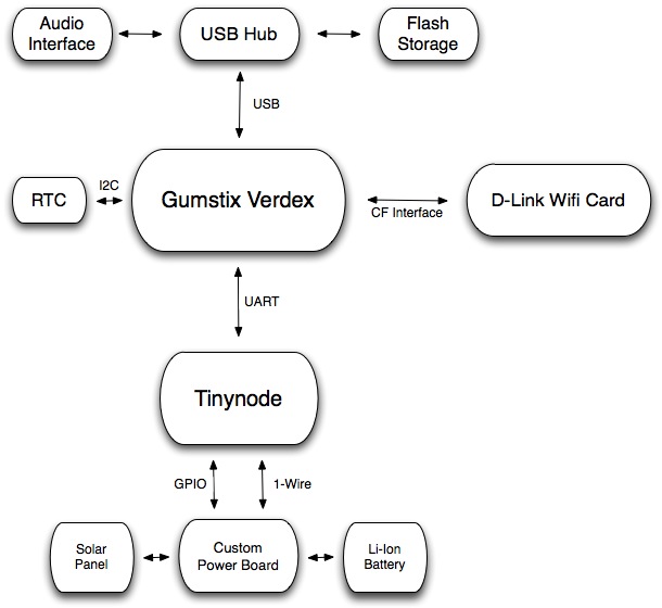
The main embedded processor used in our harvesting node is an ARM-based Gumstix microcomputer (available here). Specifically, we are using the Verdex XM4 motherboard coupled with netCF-vx and breakout-vx daughterboards. The netCF board allows a CF-Based WiFi card, while the breakout board exposes a variety of interfaces including UART, I2C, Power connections, and USB Host.
The Gumstix is connected to a custom board that allows a low-power sensor platform to toggle the power supply. Data is exchanged between the Gumstix and Tinynode via logic-level UART. An additional UART can be used to connect an embedded camera (CMUCam3, available here), although we currently do not have a rechargable power solution for the CMUCam when connected to the Gumstix.
The I2C bus is used to communicate with a real-time clock that restores the system clock after the Gumstix is brought up from an 'off' state.
A variety of peripherals can be connected via USB. We are currently using USB to connect a flashdrive that provides an additional 1GB of storage. We are also planning to use a USB audio-interface to connect a Hydrophone (underwater microphone).
A useful resource for Gumstix-related information can be found here. Here, there is good description of how to get the linux buildroot environment setup, how to flash the filesystem and kernel, power consumption characteristics of the Gumstix motherboard, etc. Currently we are running linux kernel 2.6.21. Multihop communication is achieved using version 1.5 of UC Berkeley's DTN implementation.
Tinynode
The low power sensor platform used in our energy harvesting node is the Tinynode, avaiable from a Swiss-based company called Shockfish (available here). The sensor features a low-power MSP430 microcontroller, a variable-bandwidth XE1205 radio tranceiver, and 512kb of flash. The Tinynode is used for energy monitoring, and forwarding control information through is XE1205 radio. A bit-banged 1-wire interface is used for communication with Fuel Gauge ICs, and a GPIO line to control the Gumstix power supply. One of the available UARTs is used to interface with the XE1205 radio, while the other is used to communicate with the Gumstix.
The node is programmed using TinyOS (http://www.tinyos.net). We have drivers available for TinyOS-2.x that allow the node to communicate with the fuel-gauge ICs.
Custom Power Board
The Gumstix, Tinynode, and all other attached peripherals receive energy through a custom power board. The design is a derivative of the power board used for the Turtlenet project at the UMass PRISMS lab. The primary features of the board are a pair of fuel gauge ICs (The DS2750 and DS2770)that monitor instantaneous current, accumulated current, voltage, and temperature. Two ICs are used because one measures net current flow, while the other measures consumed flow. These two values together allow you to determine the amount of charge current available. The DS2770 is used to regulate the charging of the Lithium-Ion battery from a solar panel.
The feature we added to the board is a switching boost-regulator that pulls up the 3.7V Li-Ion battery to the 4V required to operate the Gumstix. Using the enable pin of the regulator, we can cut-off power to the Gumstix.
Hardware (schematics and board layout): eaglecad files, schematic (png), board (png),
Bill of Materials
Underwater Camera
To allow underwater pictures to be captured, we have placed an embedded robotics camera -The CMUCam3- in a waterproof pelican box (specifically the 1020). Pelican states that the camera is rated for 1m submersion for 30 minutes, although we have found the case not to leak after being placed in a fish tank overnight. We drilled several holes in the case to bring RS232 out, and sealed the holes with a product called "WaterWeld". The camera is currently powered from 4x Alkaline AA batteries. We would like to feed power into the box from a power board equipped with a solar panel, but do not have a 6V power supply available. We have found the camera's batteries currently deplete after a 24Hr period after taking ~40 images (it isn't immediately clear whether this is a result of image capture or static power dissipation).
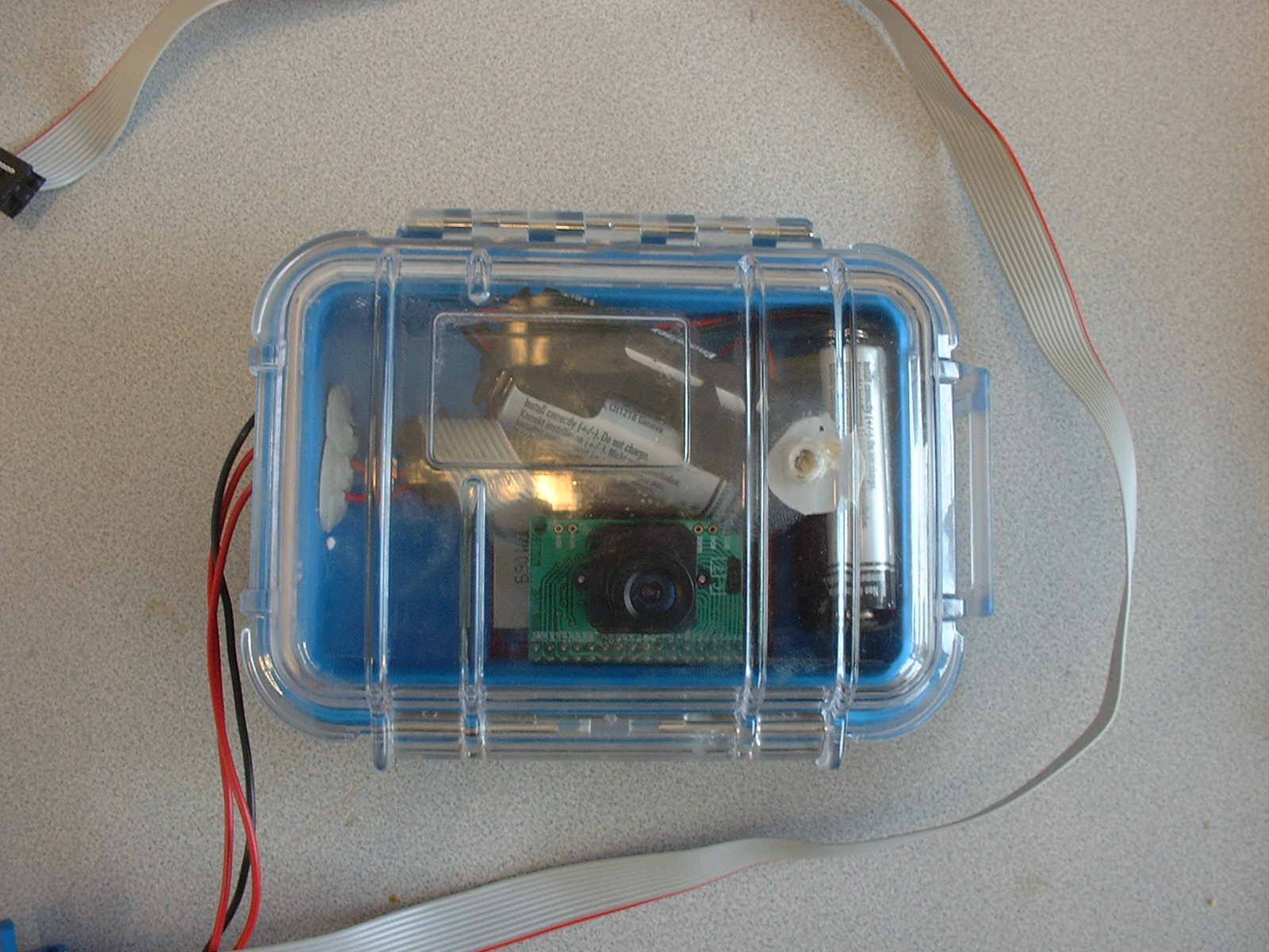
Modified Pelican case containing underwater camera
Other Parts
Other Parts we haven't mentioned in much detail are the housing used for the node itself, the solar panel, and the lithium battery.
- Battery: The battery used was purchased from Ultralife. The battery
has a nominal 3.7V output, and a capacity of 6.1Ah. The battery
voltage is pulled down to 3V by the Power Board (MAX1921 regulator) to
operate the Tinynode and pulled up to 4V (TPS61030 regulator) to
operate the Gumstix computer.
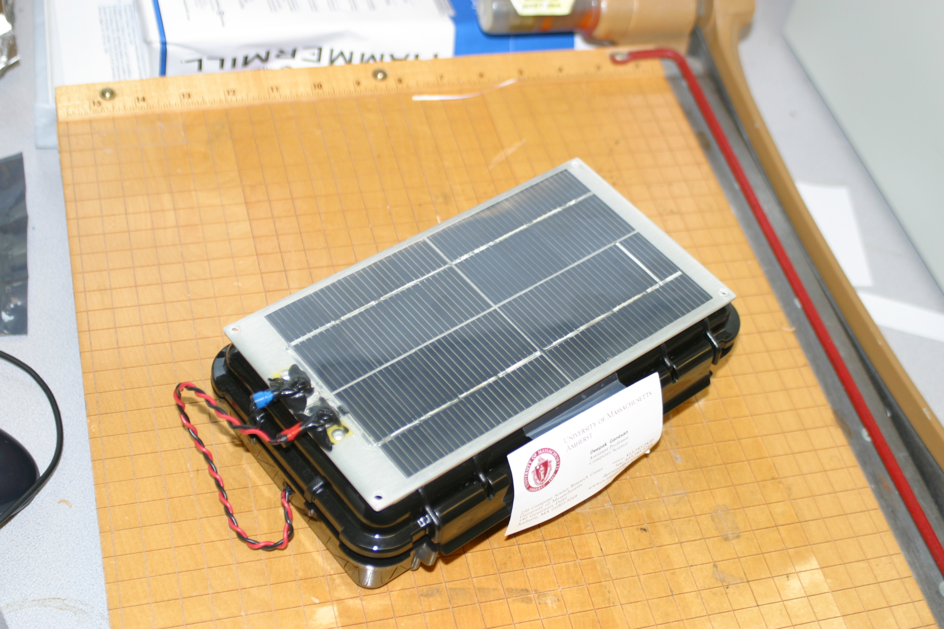
- Solar Panel: The solar panels used for our node were
purchased from Solar World,
model# SPE-350-6. They are rated for an open-circuit voltage of 9V
and short-circuit current of 350mA. Under full sunlight conditions at
noon, we have found that the panels produce ~700mW of power.
- Realtime Clock To mantain the Linux system time after
a power cycle, we make use of a DS1307 real-time clock. We initially
purchased a DS1337 based development board from Sparkfun
Electronics , but realized this RTC requires 5 volts. The DS1307
is pin-compatible with the DS1337, so we were able to swap chips by
removing the backup battery from the board (DS1337 does not use a
backup battery). This backup battery isn't necessary because our
system assumes that we will always have energy available from the
Lithium-Ion battery, and the node would fail if this energy store were
depleted. The RTC is simple to interface with the Gumstix via I2C.
The driver is available within the Kernel configuration options within
the gumstix-buildroot environment
- Node Housing All of the node components fit
comfortable inside a 1060 Pelican
Case. A node was deployed on the roof of the Computer Science
Department for a period of 4 days under fairly poor winter weather
conditions. The box contained no moisture after deployment, so it
seems sufficient for weatherproofing the electronics.
©2008 Sensors Lab, Computer Science Department,
University of Massachusetts Amherst